Two-channel laboratory instrument · User, programming and maintenance documentation
☰Overview⌄
Two-channel laboratory temperature control
Programmable heating. Clear control, from start to finish.
Control two separately powered DC heater channels with independent Omron temperature programmes, dedicated ENABLE controls and amber HEAT ACTIVE indications. Explore the equipment, plan a heating profile or open the documents you need.
2 channelsIndependent temperature control0–60 V DCExternal supply design range15 A per channelMaximum design limit, subject to verification
The Heating Rate Controller provides two independent temperature-control channels for externally powered DC heaters. Learn what each channel does, how it connects, and how to operate it under the site's approved procedure.
Control each channel independently
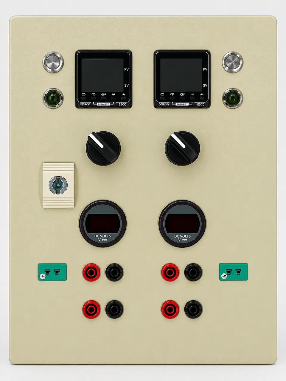
Each channel has an Omron temperature controller, a maintained CONTROL selector, a momentary HEATER ENABLE button and a HEAT ACTIVE indicator. The temperature controller monitors a Type K thermocouple and commands the heater through the control circuit.
Channel 1Channel 2
Connect the external heater supply
The red-and-black connectors are arranged in two pairs per channel. Connect the external DC supply to the upper pair marked PSU IN. Connect the heater to the bottom pair marked HEATER OUT. Use the matching green Type K connector for temperature feedback.
Specified design limits: 0–60 V DC and 15 A per heater channel. External power supplies, wiring, connectors and protection must be suitable for the intended duty and verified before use.
Before use — open electrical protection item
Neither channel’s Murata DC voltmeter has the manufacturer-specified external input-wire fusing fitted. The meter’s internal resettable fuse does not replace this protection. Do not authorise live heating until the meter input wiring and its protection have been corrected, inspected and recorded alongside the other equipment safety checks. Voltmeter protection notice and acceptance checks →
Select a numbered control or connector to learn its function and indication. For terminal-level maintenance, use the current electrical reference.
This photograph is a control-position reference, not a verified final product photograph. The finished HEAT ACTIVE indicator lamps are amber, regardless of their appearance in the image. Follow the permanently fitted panel markings and electrical reference →.
01 · channel control
Heater enable pushbutton
Panel marking
HEATER ENABLE
Operation and indications
Electrical system
Choose the task you need. The electrical reference, connection schedule, distribution allocation and component register each have one definitive location.
Understand the controller
Identify the mains supply, shared 24 V control circuit, channel enable and separate DC heater paths.
Electrical maintenance requires isolation of both mains and the external DC source, and suitable competent inspection before returning equipment to service.
Panel markings
Use this reference to identify each channel’s controls and connections. Check the permanent markings on the equipment before connecting a supply or heater.
Channel 1
Reference
Panel label
SB1
ENABLE
HL1
ACTIVE
E1
TEMP CTRL
S1
CONTROL
PV1
DC VOLTS
JTC1
TC INPUT
JP1 · upper pair
PSU IN (+ / −)
JP2 · lower pair
HEATER OUT (+ / −)
Channel 2
Reference
Panel label
SB2
ENABLE
HL2
ACTIVE
E2
TEMP CTRL
S2
CONTROL
PV2
DC VOLTS
JTC2
TC INPUT
JP3 · upper pair
PSU IN (+ / −)
JP4 · lower pair
HEATER OUT (+ / −)
Connector references used in electrical drawings
The front-panel connector references and the electrical drawings use different naming systems for the same four red/black pairs:
Channel
Front-panel reference
R1.2 drawing reference
Connection
1
JP1
JP1-IN
Upper pair — external PSU IN
1
JP2
JP1-OUT
Lower pair — HEATER OUT
2
JP3
JP2-IN
Upper pair — external PSU IN
2
JP4
JP2-OUT
Lower pair — HEATER OUT
Use the permanently fitted equipment markings and confirm the actual channel and polarity before making connections. The drawing reference is not a substitute for identifying the physical connector.
The amber HEAT ACTIVE lamp shows enabled heating demand, not measured heater current. See the electrical reference for circuit details.
Standard operating procedure
The equipment has one controlled operating procedure. Use the complete SOP for experiment setup, controller programming, energizing the external supply, heating, shutdown and abnormal conditions.
Operating checklist
The full SOP contains the required sequence, expected controls and indicators, and action to take if a check fails. Use its printable version at the test station.
The Omron programme, heater ENABLE circuit and external DC power supply are separate. Read each indication below before starting or diagnosing a test.
What each display or lamp tells you
Display or control
Meaning
Important distinction
Omron PV / SP
PV is the thermocouple temperature; SP is the current target temperature.
Neither shows measured heater current.
Omron r-r = rst
The Omron programme is in RESET.
RESET is not electrical isolation. Verify that output demand is OFF in the approved configuration.
Omron r-r = run
The Omron programme is executing.
The heater still needs ENABLE, external PSU output and actual heat demand before it can deliver power.
EAO ENABLE ring
ON: the Finder 13.61 heater-enable output is asserted. OFF: heater ENABLE is not asserted.
Does not start or stop the Omron programme; does not prove the external DC supply is isolated.
Amber ACTIVE LED
ON / pulsing: ENABLE is ON and the Omron is requesting heater drive through the Weidmüller interface.
Does not prove actual current or heating. The indicator can pulse during proportional control.
Murata DC VOLTS
Shows the matching external PSU input voltage when the input exceeds approximately 6 V.
Does not measure heater output or current. A blank display does not prove safe isolation. External input-wire fusing is currently not fitted; see the safety notice.
When should ACTIVE be illuminated?
With the specified wiring, the ACTIVE LED positive is connected to Finder 13.61 terminal 14 (EN1/EN2); the negative is switched by the relevant Weidmüller demand interface.
EAO heater ENABLE
Omron heating demand
Amber ACTIVE
OFF
OFF
OFF
OFF
ON
OFF
ON
OFF
OFF
ON
ON
ON / pulsing
This table describes the control-command indication, not whether the external PSU is switched on or whether the heater is actually carrying current.
Power interruption or unexpected indication
Abort the test after any supply interruption. Keep the external DC heater supply isolated until the ENABLE state, Omron RESET behaviour and safe restart conditions have been checked. If an indicator behaves differently from the table, stop and investigate using the approved fault procedure.
Set up the controller, create and select programmes, and find the correct menu on the front panel. The worked examples are learning aids; verify settings against the fitted Omron model and the intended test.
E5CC-T Programme Studio · builder and five-button simulator
Build a ramp, soak and step programme (up to 32 segments; memories 0–7), select any documented Omron sensor/input for OFFLINE planning, preview the commanded setpoint and inspect non-blocking sensor compatibility warnings and practise the real five-button sequence. The offline simulator retains practice programmes in the browser, separates d.prg (editing) from prg (run selection) and provides a virtual power cycle. It is for keypad practice, not simulation of real heater outputs or safety devices.
Choose the target temperature, ramp rate, hold time and memory slot, then follow the exact Omron display and button sequence one step at a time. No cable or account required.
Move through setting levels with illustrated LEVEL/MODE routes. Search every documented mnemonic, inspect parameter explanations, follow each MODE step, and view conditional hardware settings without hiding the full reference. Select the model suffix printed on the physical controller; omitted parameters depend on firmware, protection and active settings.
These instructions cover Omron E5CC-T series controllers. Check the complete nameplate and option suffix on each controller before changing hardware-dependent settings; USB identification returns only a model prefix. The step-by-step guide includes the creation, retention check and selection of example Programme 1 (50 °C at 2 °C/min and 15-minute soak), exact LEVEL/MODE steps, which settings are global, programme-wide and segment-specific, Operation Level monitors, and how to find and inspect the assigned PID parameters.
Start with the 50 °C worked example, then use the fixed 80 °C example, 120 °C ramp example and ramp calculator as further exercises. The prg selection must be checked separately from d.prg before RUN.
Omron E5CC-T — setup and autotune
Use this section when setting up a channel or checking its performance. Use the exact model suffix and firmware shown on the installed controller when choosing parameters. Hardware options and available settings vary by model.
Controller setup
Identify the fitted E5CC part number and confirm which channel is being configured.
Verify that the current input in-t matches the actual physical sensor, its permitted range/resolution, the units and the global upper/lower SP limits. The Windows app can plan other documented sensors, but cannot identify the external probe by USB.
Check that the displayed process value is plausible and that sensor errors are handled correctly.
Confirm the control method, heating direction and output assignment for the installed SSR drive circuit.
Check the control period, required limits and any configured alarms.
Enter and read back the approved programme using d.prg and segment fields. Then, in Operation Level RESET, select the intended RUN programme using prg and verify pgsg.
Record the final configuration and confirm it independently for the other channel.
For full button-by-button instructions, open the linked E5CC-T programming guide. Verify the settings on each physical controller during commissioning.
Autotune procedure
Only start autotune after commissioning, with the real heater, thermocouple placement and representative thermal load in place.
Assess the risk of temperature overshoot and confirm the independent safeguards before tuning.
Choose an appropriate tuning target and begin the Omron's autotune function as specified in its user manual.
Leave the arrangement stable while tuning operates. Do not change the test load or sensor positions.
When tuning finishes, record the resulting control settings and evaluate a controlled heating response.
If temperature oscillates or overshoots excessively, stop and investigate rather than repeatedly retuning.
Autotune is not a substitute for verifying safety limits. It is unsuitable during an actual thermal-runaway event.
Use the instructions matching the controller's exact part number and firmware. Match parameters to the fitted controller, sensor and intended heating test.
Windows USB Setup Studio
Use the Windows application to prepare a local programme, read a single Omron E5CC-T controller using E58-CIFQ2, review applicable settings and carry out deliberate, verified transfers. The application does not monitor live heater current, provide electrical isolation or replace commissioning checks.
Prepare without the USB cable
Create or edit any of eight local programme drafts, each with up to 32 ramp/soak/step segments. The profile can be graphed and exported even when its target exceeds the chosen controller sensor range; the app gives an explicit warning instead of discarding the entered temperature.
Choose among 30 documented input codes (0–29): Pt100, JPt100, supported thermocouple/IR types and analogue current/voltage. The last group needs configured signal scaling (C3:0001–0003); do not label it in °C unless that is the actual engineering unit.
USB 0503 returns only a 10-character prefix, for example E5CC-TQX3A. It does not identify 5M or the final -NNN option code. Check the printed nameplate and choose its exact full model in the Windows dropdown.
The app uses the documented model option matrix to show only plausible event input, CT, RS-485, transfer-output and other option settings. An option still needs a successful actual register read and a qualified write procedure; selecting it is not proof of physical fitment or wiring.
Read the USB model prefix and controller status; confirm the nameplate suffix for this connection. Start in read-only mode; enable writes only during an authorised isolated setup procedure.
2
Read and back up
Capture all eight DA programme memories (150 registers each) and supported C0/C1/C3/C5 settings. Failed or unavailable hardware options are not interpreted as zero. Retain the backup and recorded controller identity.
3
Edit programme
View the commanded SP curve, edit freely and compare all targets against the actual verified input range, decimal resolution and sl-h/sl-l limits. A conflict produces a warning and an offer to propose a compatible global sensor range, never an automatic rewrite.
4
Review controller settings
Optional hardware parameters follow the confirmed full model and successful readback. Programmes, sensor choices, PID parameters, output assignments and safety settings are not all interchangeable write operations; unsupported or hazardous changes are kept read-only.
5
Apply and verify separately
For a proposed C3 input change, preview the exact selected registers, isolate heater supplies, apply/read back in setting area 1, use Finish + Return to normal, visually verify normal PV/SP, then reconnect and perform a fresh Step 2 read/backup. Only then preview, write RAM, verify, save and finish the selected DA programme. Do not confuse CMW OFF with leaving setting area 1 or with heater disable.
Sensor selection affects every programme: the Omron's existing DA words may acquire different physical meaning after changing input resolution even though the raw memory does not change. The app must not silently rescale any of the eight stored profiles. Physical sensor compatibility, output-off state at RESET, and power-return inhibition remain independent commissioning checks.
The portable Windows package has separate read-only and isolated-setup launchers. Selecting a launcher does not itself authorise controller writes or heater operation.
Component register
Look up an electrical designation, manufacturer part number or replacement item in the single searchable component register.
Parts and manufacturer data
Includes controllers, relays, SSRs, protection, switches, indicators, terminals, connectors and manufacturer documentation.
Safe operation depends on verified controls, heater connections, independent external supply isolation and protection for each installation and test.
Before service or a new installation
Isolate and prove dead on both the mains inlet and the separate 0–60 V DC heater supplies. Maintain cabinet and door protective-earth bonding, verify the specified component ratings, and ensure the heater-off state and power restoration are tested. The Murata input-fusing discrepancy must also be resolved and recorded before live operation.